First, check to make sure your repair kit is complete. See component list above.
Door Panel Removal:
(This tutorial was performed on a 2005 E150 van. Other years and versions may vary. Search YouTube for your model year)
Photo 1 shows the top half of the rear cargo door panel, passenger side of the van. On these vans, the lock cylinder is located in the lower corner of the license plate holder, so this panel must be removed to get at it.
Note: Every effort is made to accurately portray the installation
process. However, sometimes the vehicle manufacturer makes changes that
affect the steps in door panel removal or installing our product. Use
this tutorial as a guide only. If you are not certain of your ability,
refer installation to a professional.
Work carefully and take notes or make sketches to help you put the door back together properly.
Use a small tray to store screws and parts removed so they don't get lost.
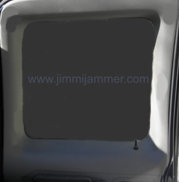 Photo 1
Photo 2
The rear door panel consists of 2 pieces, upper and lower. Remove the top half first.
Start by unscrewing the cap on the lock rod sticking out of the panel below the window.
Remove the upper trim panel, it is held in place with snap clips.
Start on any edge and pull panel away from door. Pull straight out, away from the door.
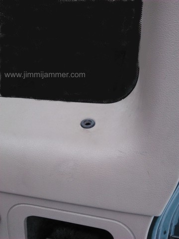 Photo 2
 Photo 3
Top half has been removed.
Next, remove 2 screws from pull handle and screws along the perimeter of the panel. There are some near the top edge and usually some along the bottom edge.
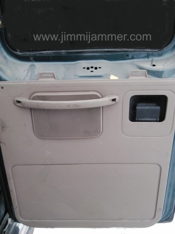 Photo 3
 Photo 4
Once all the screws are out, the panel should lift up and away from the door metal.
If it doesn't come up easily, look for more screws, or on some years there may be snap clips as well.
Note: In cold weather the plastic tends to be brittle. It is better to work in warm conditions to avoid cracking of the plastic.
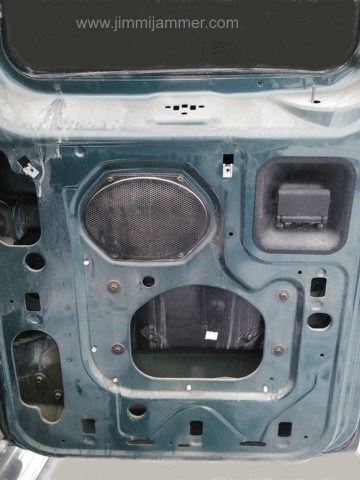 Photo 4
 Photo 5
There are several of these hooks on the back of the panel.
To remove the panel, pull straight up, then away from the door..
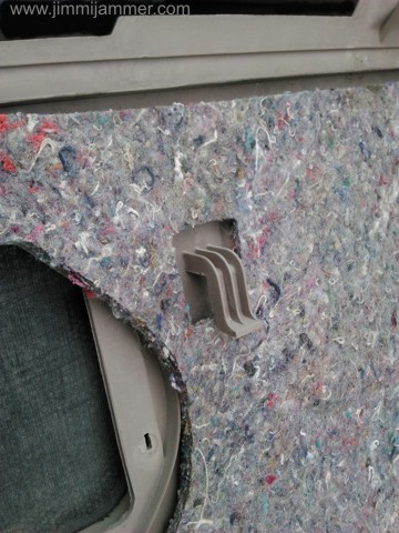 Photo 5
 Photo 6
Remove the license plate holder by removing 4 screws from corners of holder.
Not shown, there will be a lamp in the top of the frame that you must disconnect to get the frame out of the door.
If there is no connector, you may be able to take the bulb out of it's holder in the frame.
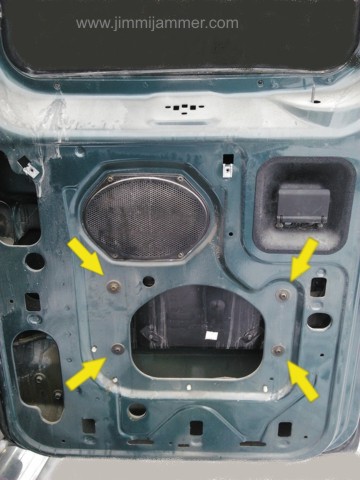 Photo 6
Disconnect the lock rod from the lock pawl.
Here is a trick to help disconnect the lock rod from the lock pawl:
Photo 7
Use a stubby screwdriver, or even a small diameter bolt, and push the round shaft into the open end of the lock pawl to bend the locking tabs up.
At the same time, push the lock rod toward the screwdriver, and pull both out of the lock pawl at the same time.
Put the screwdriver shaft into the pawl where the yellow arrow points, then push in the direction of the two red arrows. Photo 8.
This will prevent breaking the locking tabs on the lock pawl and help get the rod out more easily.
With the lock rod and license plate lamp disconnected, you should be able to remove the license plate holder from the door.
Much of the following work can be done easily on the bench.
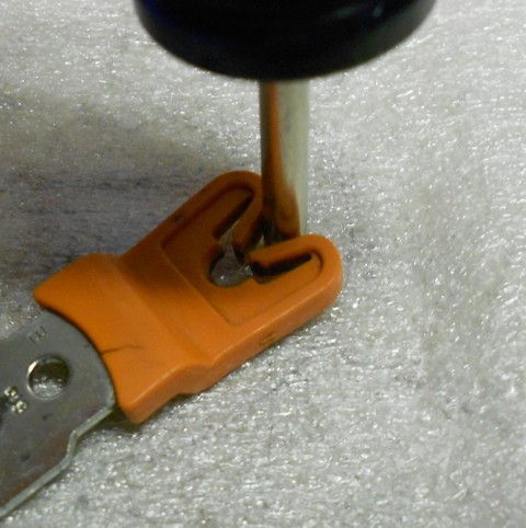 Photo 7
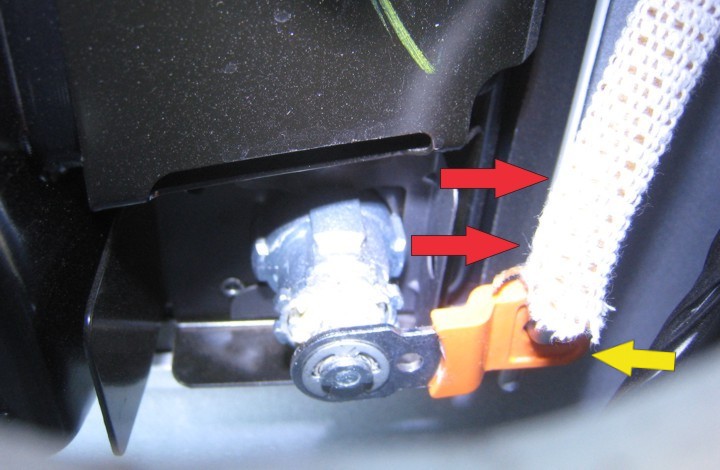 Photo 8
Photo 9
Note: Steps 9 - 11 are for licence plate frames that do not have the metal reinforcement plate from the factory. These steps use our reinforcement plate provided with the kit.
If your frame has the metal reinforcement from the factory, skip to step 12.
Remove the factory spring clip that holds the lock in place.
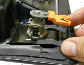 Photo 9
Photo 10
Place the provided flat support plate from the kit around the lock body.
If your frame has the factory metal backing, do not use this plate as the clip will not fit with the added thickness.
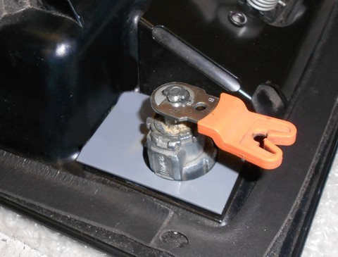 Photo 10
Photo 11
Remove two screws from the open end of the provided security clip. This is necessary so the clip can slide onto the lock body. Again, only use the small backing plate if your van does not have the reinforced metal already on the license plate frame in the lock mounting area.
The open end of the clip slides into the same grooves on the lock body that the factory spring clip used to hold the lock in place.
Get the clip started making sure the lock is in position. The set screw at the back end of the clip open end must be threaded out enough to allow the clip to slide on over the support plate.
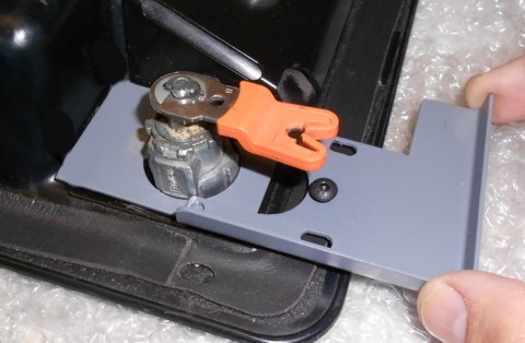 Photo 11
 Photo 12
This photo is only to show how the open end of the clip fits into the grooves on the lock body.
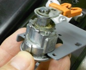 Photo 12
Photo 13
Push the security clip toward the center of the license plate holder until the closed end is against the lock body.
You may need to use the key in the lock to move the lock pawl up or down so you can tighten the back set screw. Tighten just snug now.
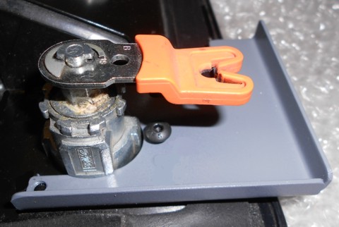 Photo 13
 Photo 14
Put the other two screws in the ends of the clip that were removed earlier. Use a drop of thread adhesive, such as loctite, so they won't loosen over time.
Test the key in the lock. Make sure the lock doesn't turn in the holder. It should all be tight and secure.
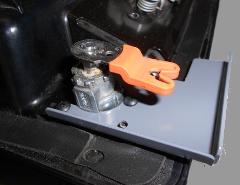 Photo 14
 Clean a spot for the warning label. Put the warning label ni the desired location.
That's it!
If you have encountered significant differences with your installation experience, please let us know via our Contact Page.

All text and graphics property of
Redline Technical Group, Inc.
© 1998 - Current
Do not use without permission.